Restauración Yamaha MX-1000. Parte II
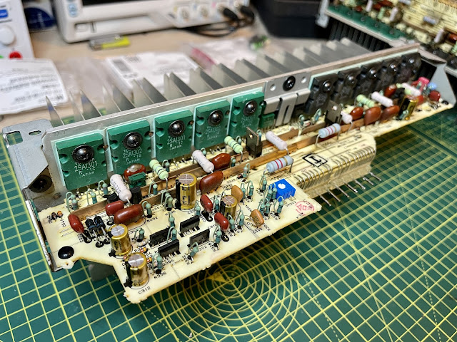
En la segunda parte de esta puesta a punto (primera parte aquí), nos centraremos en las placas de potencia situadas en la parte de abajo del amplificador, accesibles una vez retirada la cubierta inferior.
Estas placas contienen las siguientes partes del circuito:
APS: Para aumentar la eficiencia, solo se aplica aprox 40V simétricos a los transistores de potencia de audio. Un comparador se ocupa de monitorizar la tensión de salida, y cuando se aproxima al limite, la fuente aumenta progresivamente la tensión de alimentación hasta un máximo de 94V por rail. De los 10 transistores de potencia que se observan en cada una de las placas, 6 son de audio y 4 son de alimentación.
En este ejemplo se puede ver en funcionamiento. Es similar en cierto aspecto a un clase G mas refinado.
I-AMP: Transistores de potencia de audio que entregan la corriente necesaria a la carga.
HCA: Yamaha Hyperbolic Conversion Amplification. Este circuito, simplificando mucho, es una variante de bias dinámico (otros fabricantes de la época han implementado soluciones similares bajo distintos nombres comerciales) que busca minimizar la distorsión de un AB convencional, intentando aproximarse a un clase A sin los problemas de eficiencia de estos últimos.
Douglas Self, en su libro Audio Power Amplifier Design, hace mención a esta topología:
Yamaha did not want to be left out of the non-switching business. Their version was called Hyperbolic Conversion Amplification (HCA). The implication seems to be that two hyperbolic curves can be combined to give a straight line; this is not true mathematically as far as I am aware, though certainly two parabolas (square law curves) can be combined to result in a straight line. The relevant patent appears to be 4,803,441 by Noro,47 which references an earlier patent by Yamaguchi, 48 and confirms that HCA is based on square law characteristics. More hyperbole than hyperbolic, I feel. HCA was applied to the Yamaha MX-1000 amplifier in 1989; it was also applied to the MX-2000 (1988) though the details of the circuitry are rather different. A simplified version of the MX-1000 application is shown in Figure 4.22. A and B are sub-rails which are driven up and down with the output by C2 and C3. Biasing diodes D1, D2 set up a constant current in the current-mirror Q9, Q7, while D3, D4 do the same for current-mirror Q10, Q8. The signal is applied through the voltage amplifier, which has a low output impedance, and is converted from voltage to current by R15, which sees a low impedance at the emitters of Q7 and Q8. The output current from mirror Q9, Q7 is bounced off the upper sub-rail A by mirror Q5. Q3, and likewise the output of mirror Q10, Q8 is bounced off the lower sub-rail B by mirror Q6, Q4. The output current from Q3 is fed to amplifier Q1, which is also fed with a version of the output signal, and Q1 controls driver Q11. Likewise for the lower half of the circuit. The output stage itself is a conventional Type II emitterfollower configuration. The fundamental principle is that the product (not the sum) of the output currents from Q7 and Q8 is constant. Therefore, no matter how hard the circuit is driven, the smaller current never reaches zero, and therefore the output devices never turn off.El primer paso es extraer las placas de la pcb principal. Para ello se deben desoldar los pines que la unen a ella:
Estas pistas son bastante delicadas, y es relativamente fácil dañarlas. El consejo aquí es controlar la temperatura del soldador, y nunca sobrecalentar la pista. Una vez succionado el grueso del estaño (una buena bomba manual sirve perfectamente), se calienta el pin y haciendo una pequeña palanca se levanta con cuidado para separarlo de la pista.


Comentarios
Publicar un comentario